Wiring Diagram Remote Control Light Switch
The green wire, a ground wire, connects with the green screw in the switch or the electrical box. Connect the 2 ground wires with a fourth wire nut.
Flashlight Controlled Remote Control Switch Circuit

• the switch is already at the light level the pico remote control is sending.

Wiring diagram remote control light switch. This guide will teach you how to install a remote control light switch in five easy steps. A wiring diagram is a streamlined standard pictorial depiction of an electrical circuit. If the module need to work with on/off toggle switch.
With this sort of an illustrative guide, you will have the ability to troubleshoot, avoid, and total your tasks without difficulty. With exasperating to remove, replace or fix the wiring in an automobile, having an accurate and detailed yam remote. 1 trick that we 2 to printing a similar wiring plan off twice.
X10 remote pool light switch wiring diagram. When you make use of your finger or perhaps the actual circuit with your eyes, it is easy to mistrace the circuit. The difficulty in fact is that every car is different.
If the module doesn't need to work with on/off toggle switch. The common elements in a wiring diagram are ground, energy, wire and connection, output devices, switches, resistors, logic gate, lights, etc. This diagram illustrates wiring for one switch to control 2 or more lights.
Switched lines and neutral connect to a 3 wire cable that travels to the lightfan outlet box in the ceilingthe fan control switch usually connects to the black wire and the light kit switch to the red wire of the 3 way cablein this diagram the black wire of the ceiling fan is for the fan and the blue wire. To make sure they are turned off, flip the breakers until the light goes off. Switch wiring indiamart deutsch control fan fans diagram.
The light switch has three wires. It fits in the standard toggle style switch wall plates and is simple to operate and install. Wiring diagram for ceiling fan with light switch.
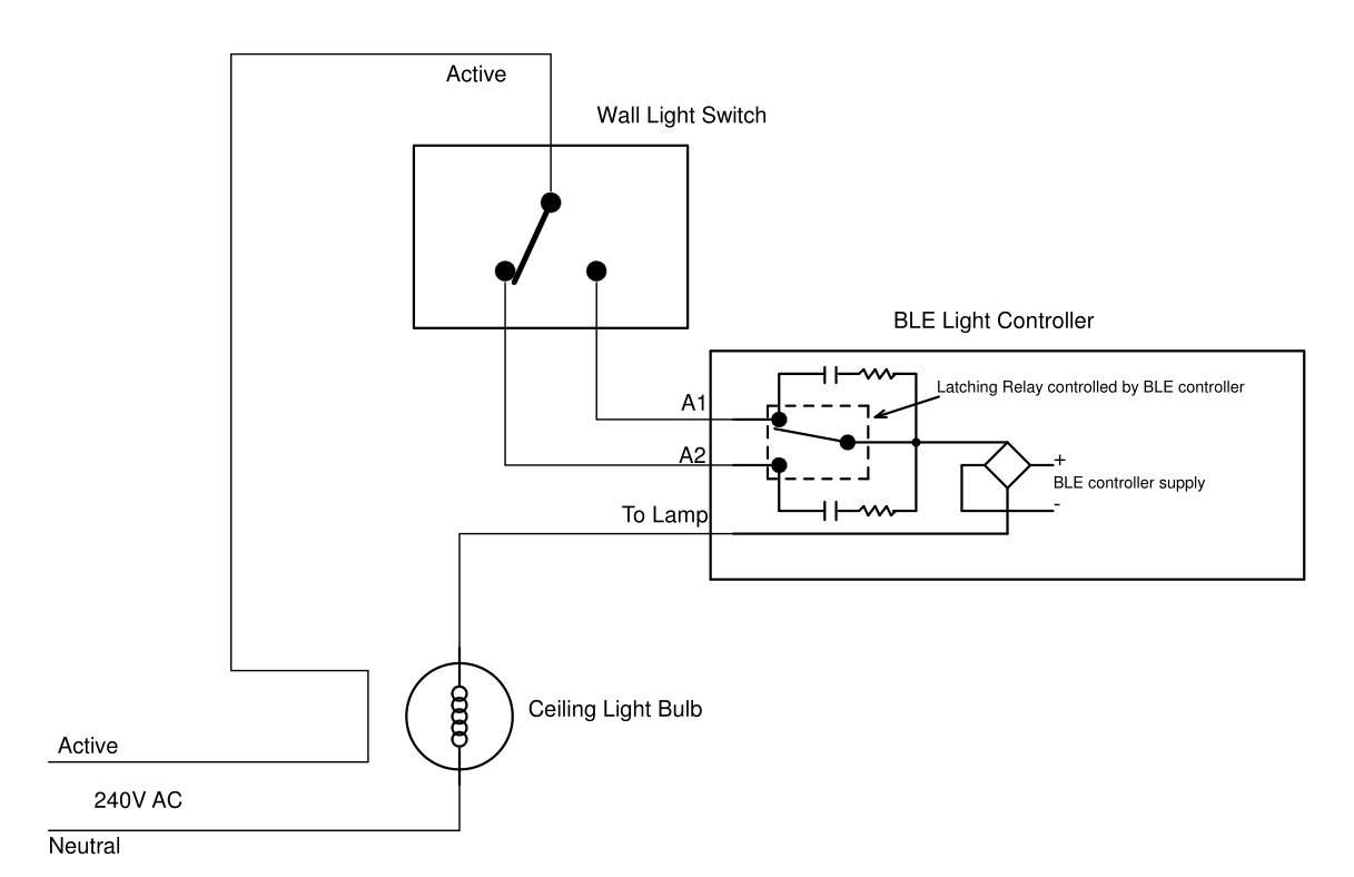
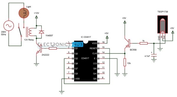
Pin di pedro costa su electric. During the downward position the lighting input terminal c will be connected to the output terminal a and the current flows from lighting circuit to lamps and it starts glowing. In this remote controlled switch circuit we are using tv remote to on/off the ac light by pressing any button of remote, and using the tsop1738 at.
Print the wiring diagram off plus use highlighters to trace the signal. Basically transistor is a type of semiconductor device. Subsequent to infuriating to remove, replace or fix the wiring in an automobile, having.
The red wire is the ungrounded hot conductor from one switch while the black wire is the ungrounded hot conductor from the other switch. For the light to be controlled by a switch that’s separate from the fan, the wiring between the switch and the fan unit needs a fourth conductor, a red wire to carry the hot feed for the light kit.turn off the circuit breaker at the breaker panel that provides power to the ceiling fan circuit. The trouble in point of fact is that every car is different.
However, if the remote switch is on but the battery voltage drops, the relay will open and cut off the inverter, despite the remote switch still being on. A list of electrical symbols and descriptions is available about the “electrical symbol” page. Hunter ceiling fan switch wiring diagram ceiling fan wiring ceiling fan motor ceiling fan switch.
If they were numbered 1,2,3,4 from top to bottom. The white is also known as the neutral wire, and this wire connects with the silver screw. The wiring instructions for your new hunter fan differ slightly based on the type of wall switch and your fan’s control system (pull chain, remote control, etc.).
Here we will build a infrared light switch with remote control which can be operated wirelessly using any ir remote like tv remote, ac remote etc. Tsop output is active low, means it becomes low when ir is detected. The black or sometimes red wire, also known as the hot wire, goes into the brass screw.
Leviton light switch wiring diagram single pole wiring diagram is a simplified agreeable pictorial representation of an electrical circuit. • fass on the switch is in the off position. Wiring diagram for double control switch.
I pinimg com 564x 94 fe b5 94feb5846624592121e9. The two 'inner wires' on the right side are connected to 110v ac, the two 'outer wires' go across the load (labeled x in the drawing on your picture. See pairing the switch and pico remote control.
The colors of the wires seem to be different from switch to switch. • the switch failed to pair with pico remote control; If the module need to work with 2 way switch.
Light does not respond to pico remote control. Wiring schematic diagram for fan connection from two control switches. 2&3 are the 110v ac input and 1&4 are the load.
Wiring diagram for normal on/off control. With this kind of an illustrative guide, you will have the ability to troubleshoot, stop, and full your tasks without difficulty. This means that you will have black red white and bare.
The hot and neutral terminals on each fixture are spliced with a pigtail to the. This diagram illustrates wiring for one switch to control 2 or more lights. This wiring diagram illustrates the connections for a ceiling fan and light with two switches a speed controller for the fan and a dimmer for the lights.
Wiring diagram dimmer and fan light kit ceiling fan wiring ceiling fan with light ceiling fans without lights. Wiring diagrams july 20, 2021 05:05. Turn off the breaker to any light switch where you plan to install a remote lighting system.
Simply press the button to control the light locally or use any x10. Light switch diagram power to light. The latter, being normally closed, leaves control of the inverter to the remote switch.
• the pico remote control is outside the 30 ft (9 m) operating. Hunter ceiling fan with remote wiring diagram print the wiring diagram off and use highlighters to trace the circuit. What i don't know is which of the four conductors in the renogy switch wire is the hot leg of the switch.
Wiring diagram for one way switch.
How To Wire A, Light Cleaver Wireless Dc Remote Wiring Diagram, Unusual 220V Switch Chromatex Rh

Wiring order for A Traveller Remote Control Awesome Wiring Diagram Image

Remote Control Light Fan Switch Circuit Diagram
Remote Controlled Light Switch Retrofit with Manual Override and No extra writing.
Remote Control Light Switch Circuit Diagram

Control4 Light Switch Wiring Diagram WIRGRAM

Remote Control Light Fan Switch Circuit Diagram
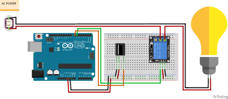
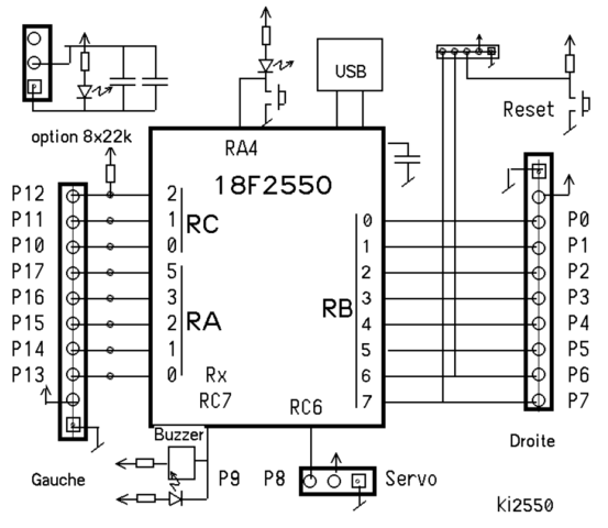
Arduino Remote Control Light Switch Code and Wiring Diagram
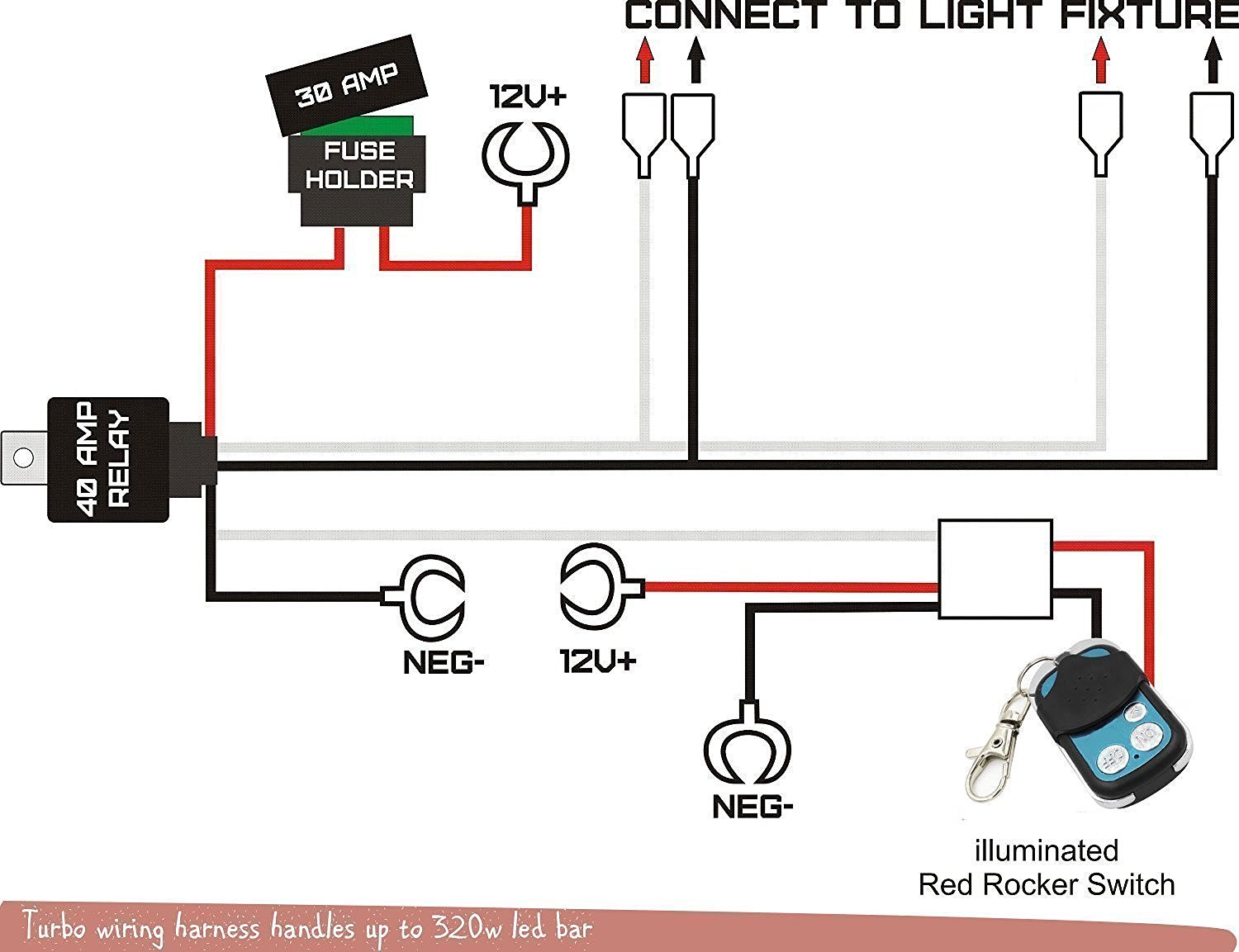
12V Wiring Harness Kit Strobe Remote Control Switch For LED Light Bar 1 Lead eBay
Remote Control Light Fan Switch Circuit Diagram
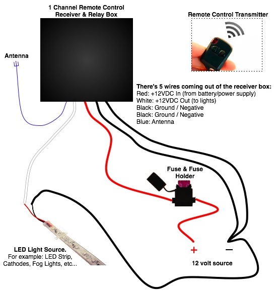
Customer Questions 12v Wireless Remote Control On/Off LED
X10 Remote Pool Light Switch Wiring Diagram
How To Wire A Light Motion Sensor Cleaver Security Light Wiring Diagram Motherwill, Rh

X10 Remote Pool Light Switch Wiring Diagram

22" 32" 42" Curved LED Work Light Bar Combo Switch Remote Control Wiring Offroad eBay
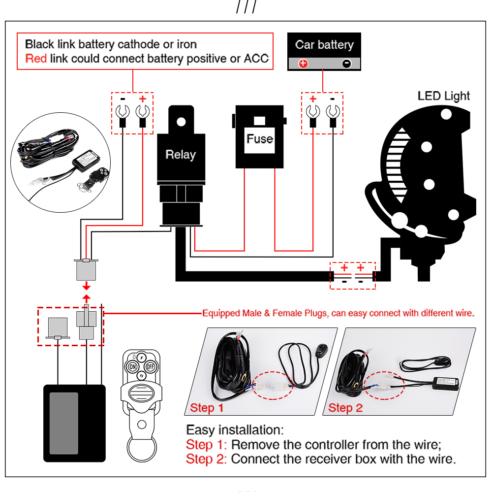
Led Light Bar Switch Wiring Diagram Wiring Diagram Schemas

Remote Control Light Switch Circuit

Two 4 channel AC 220V wireless receivers & two transmitters remote control light on/off Remote
Ultrasonic Remote Control Light Switch Circuit Car Wiring Diagram
