Ground Fault Wiring Diagram
Home electrical wiring includes 110 volt outlets and 220 volt outlets and receptacles which are common place in every home. Ground connection diagram is shown separately.
Ground Fault Receptacle Wiring Diagram Free Wiring Diagram
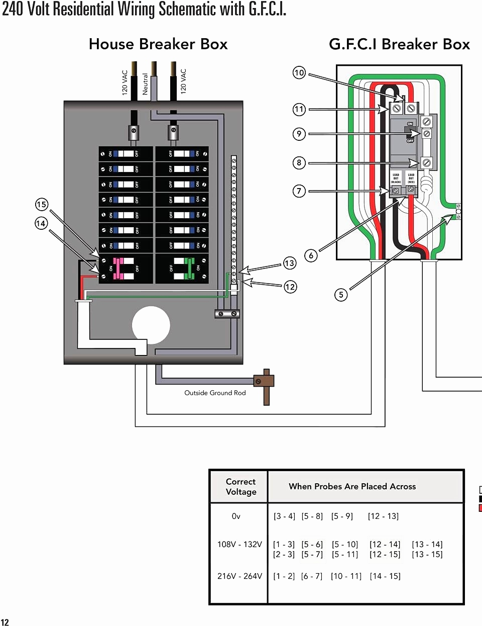
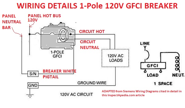
This diagram illustrates wiring for a circuit breaker with a built in ground fault circuit interrupter or gfci.

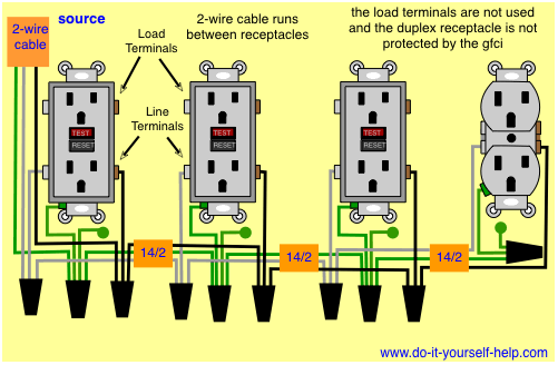
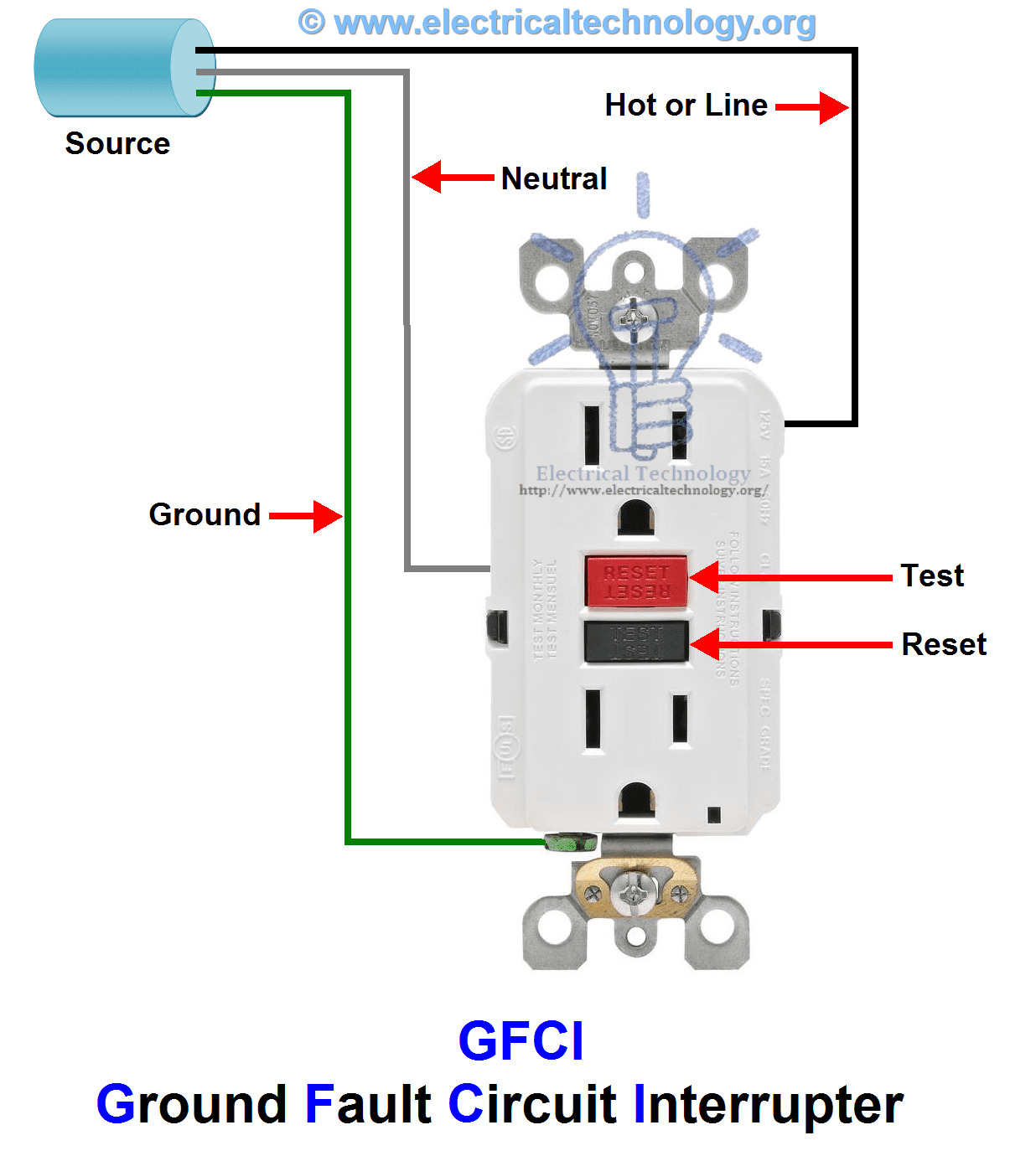
Ground fault wiring diagram. Ground connection is not shown. Injunction of 2 wires is generally indicated by black dot on the junction of two lines. • the white wire connects to the gfci white lead.
Hot tub wiring diagrams use a gfci disconnect designed for 240v hot tubs 4 or 3 wire spa types. Wiring diagram for 240 volt gfci breaker. Power is connected to the gfci line side.
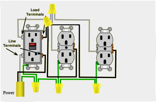
Connect the load (receptacle) cable wires to the gfci load leads: By connecting the switch to the load terminals on the last gfci, the switch and light are protected against ground faults as well. This diagram illustrates the wiring for a circuit with 2 gfci receptacles followed by a light and switch.
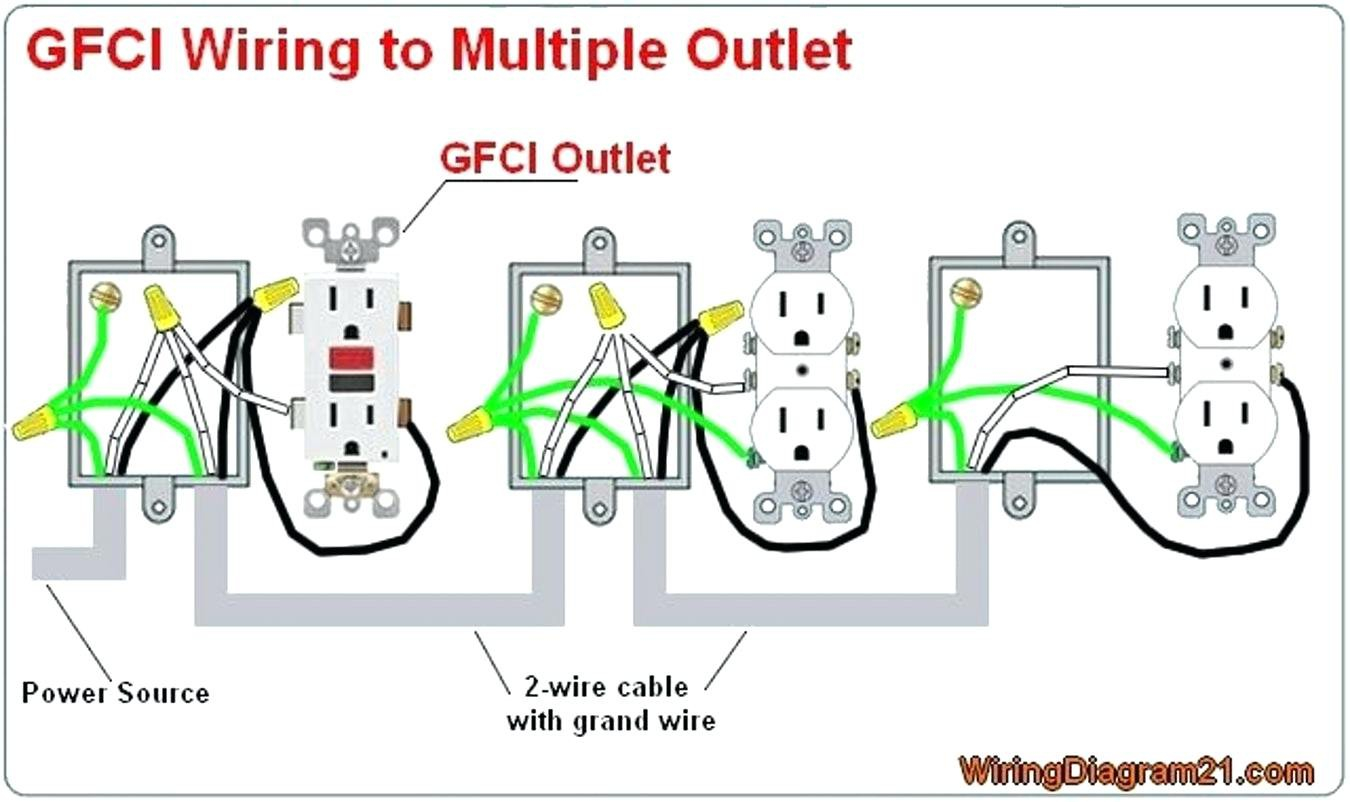
In addition, wiring diagram gives you enough time frame by which the tasks are for being finished. This gfci wiring method may be found in a bathroom or kitchen where the switch may be near a water source. Connect the bare ground wire to the green (ground) screw.
Control 240 volt with wemo light switch wiring outlet wiring wall outlets This kind of circuit is used for dishwashers, whirlpool spas and other locations where water contact is likely. The two 120v circuits drive the pumps aerators lights timers etc.
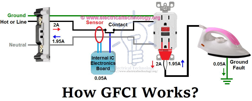
This diagram illustrates wiring for a circuit breaker with a built in ground fault circuit interrupter or gfci. Replace the receptacle, screw it back into the box, and attach the cover plate. We are now studying wiring of gfci and how it connects to light the bulb as also shown in figure.
This 20 amp, volt breaker is a form of gfci that can be installed at the circuit source. Bathroom gfci outlet wiring diagram. This page contains wiring diagrams for a ground fault circuit interrupter (gfci) with a built in switch, often called a gfci outlet switch combo.
Occasionally, the wires will cross. Light switch controls an outlet in the same box. By iot | october 21, 2021.
And again, these switches are located in the middle of a circuit. Plug a clock radio or light into the outlet. • the white wire connects to the gfci white lead.
Outlets on same circuit diagram outlet wiring electrical wiring gfci. The toggle switch in the combo switch outlet controls the first light bulb while the single way. From the light switch, the circuit wiring may extend to the location of the light fixture where the typical connections are made with the circuit wires and the wires of the light.
The lower four terminals and ground wire of rcbo has been connected to the spa control box by the following sequence. Wiring diagrams for ground fault circuit interrupter receptacles gfci electrical wiring home electrical wiring. Ground fault plug wiring diagram wiring diagram is a simplified up to standard pictorial representation of an electrical circuit.
• remove the yellow sticker wrapping the leads. Gallery of wiring diagram for 220v plug data 30a 250v perfect one of these conductors is ground. Gfci wiring diagram with switch.
• the black wire connects to the gfci hot lead. Wiring diagram for a switched gfci outlet outlet wiring home electrical wiring wiring outlets. This diagram illustrates the wiring for a circuit with 2 gfci receptacles followed by a light and switch.
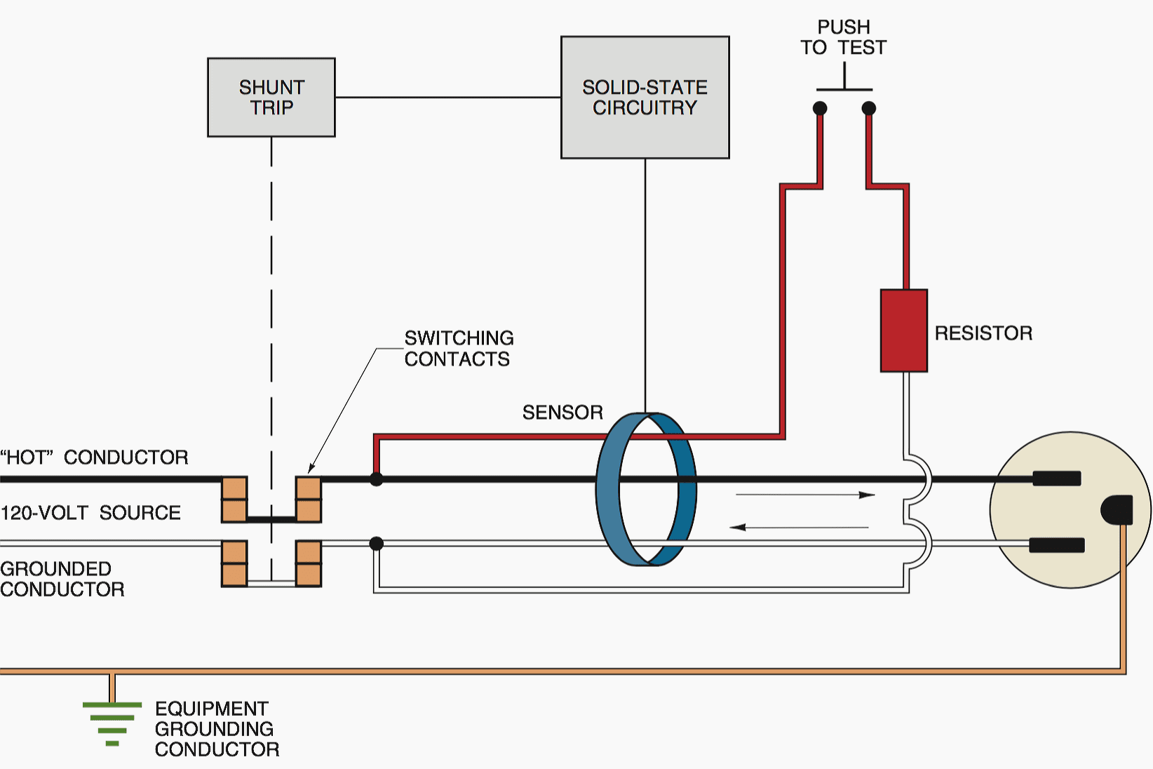
There will be main lines that are represented by l1, l2, l3, and so on. The three phase wiring for gfci or rcd (rccb) or rcbo wiring diagram shows the three lines (l1, l2 and l3) and neutral has been connected as input to the rccb from main board followed by mcb i.e. It means, all the connected loads to the load terminals of gfci are protected.
Anko gfci outlet 20 amp ul listed led indicator tamper resistant weather receptacle indoor or outdoor use with decor wall plates and s online in vietnam b08n5hj337. Gfci receptacle and switch same box electrical wiring home electrical. But, it does not imply connection between the wires.
This device can be used for ground fault protection near water sources such as in a kitchen or bathroom where space is a minimum and both devices are needed. ( see diagram a ). This diagram illustrates wiring a gfci receptacle and light switch in the same outlet box a common arrangement in a bathroom with limited space.
Wiring a gfci outlet with diagrams pro tool reviews. Gfci wiring diagram with switch. Test the gfci by pressing the black “test” button on the outlet.
How to wire a gfci breaker the river pool is rooted in italian engineering tradition balboa application notes 240 volt omegadiamond electrical requirements two men and spa dolly square d homeline 50 amp 2 pole circuit hom250gficp wiring 20 doityourself com community. Protected receptacle (s) will be connected to the gfci load side as shown below. *line and load terminal locations can differ between gfci receptacle brands.
In this gfci outlet wiring and installation diagram, the combo (switch + outlet), spst (single way) switch and ordinary outlet is connected to the load side of gfci. According to earlier, the traces at a gfci breaker wiring diagram represents wires. You may be capable to know precisely if the projects needs to be finished, which makes it much easier for you to properly manage your time and efforts.
• the black wire connects to the gfci hot lead. Insert wiring then factory sealed chamber into device box with internal test and. Cover the two single pole light switch device with an outlet cover plate.
Ground fault plug wiring diagram wiring diagram is a simplified up to standard pictorial representation of an electrical circuitit shows the components of the circuit as simplified shapes and the gift and signal friends amongst the devices. Leviton 20 amp 125 volt combo self test blank face gfci outlet white r98 gfrbf 0kw the. Wiring a gfci circuit breaker.
Wiring Diagrams for Ground Fault Circuit Interrupter Receptacles

Receptacle Ground Fault Circuit Interrupter

NEC Standard and the Ground Fault Circuit Interrupter

Ground Fault Circuit Interrupter Installation GFCI Electrical Contractor
Ground Fault Wiring Diagram Decoration Ideas
Ground Fault Receptacle Wiring Diagram Free Wiring Diagram

Wiring Diagrams for GFCI Outlets
Slater Ground Fault Outlet 5938 Wiring Diagram

Ground Fault Receptacle Wiring Diagram Download Wiring Diagram Sample
GroundFaultCircuitBreakerandElectricalOutletWiringDiagram.png (1225×879) death by

Ground Fault Circuit Interrupter Wiring Diagram Wiring Diagram And Schematic Diagram Images

What is GFCI and How it Works? Ground Fault Circuit Interrupter
What a ground fault circuit interrupter does and what it does not do EEP
Electrical Engineering World GROUND FAULT CIRCUIT INTERRUPTER (gfci) Outlet Wiring Diagram
%2BOutlet%2BWiring%2BDiagram.jpg)
Ground Fault Circuit Interruptors, GFCIs Definition Peformance Electrical Codes
GFCI (Ground Fault Circuit Interrupter) vs. Circuit Breaker Another Perfect Pool News

Ground Fault Circuit Williams Electric 510 3395601
GFCI Ground Fault Circuit Interrupter. Types & Working
Ground Fault Receptacle Wiring Diagram Download Wiring Diagram Sample